
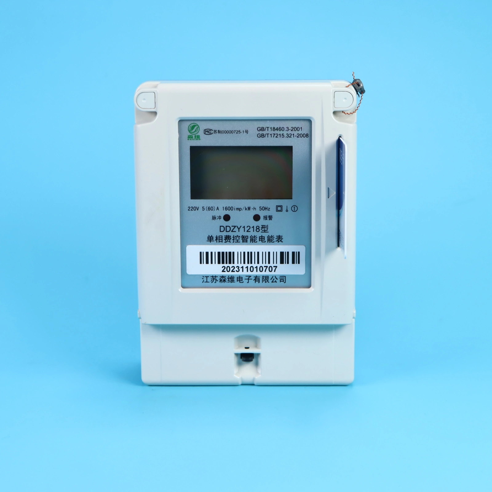
Specifications and main parameters
Standard reference voltage:
|
Electricity meter access line mode |
reference voltage (V) |
|
direct access |
220 |
Standard reference current:
|
Electricity meter access mode |
standard value (A) |
|
direct access |
5,10,20 |
Maximum current: not less than 4 times of reference current.
Reference frequency: 50Hz.
Power dissipation:
Voltage lines:
Under the reference voltage, reference temperature and reference frequency, the active power and apparent power consumption of the voltage line of the electricity meter shall not be greater than 1.5W and 10VA in the non-communication state; and shall not be greater than 3W and 12VA in the communication state.
Current circuit:
Under the basic current, reference temperature and reference frequency, the apparent power consumption of the current line of the electricity meter is less than or equal to 1VA.
Constant of electricity meter:
|
|
voltage (V) |
maximum current (A) |
Constant (imp/kWh) |
|
Single phase direct current |
220 |
60 |
1600 |
Note: The above is the recommended constant. If the user has special requirements, the user requirements shall be followed
Accuracy class:
Level 1/2
Environmental conditions
Reference temperature and reference relative humidity:
The reference temperature is 23℃, and the reference relative humidity is 40% ~ 60%.
Operating temperature range
|
Scope of work as defined |
--25℃~60℃ |
|
Limits of operation |
--40℃~70℃ |
|
Storage and transportation limits |
--40℃~70℃ |
Working relative humidity: not greater than 95%
Potential:
When the reference voltage of the energy meter is applied to 115% of the current line without current, the energy meter test output does not produce more than one pulse.
Percentage error
Under the specified reference conditions, the percentage error of the electricity meter shall not exceed the provisions in the following table.
|
load current |
power factor |
Error limit of electricity meter (%) | |
|
Level 1 table |
Table 2 | ||
|
0.05Ib≤I<0.1Ib
|
1.0
|
±0.9
|
±1.5
|
|
0.1Ib≤I≤Imax
|
±0.6
|
±1.0
| |
|
0.1Ib≤I<0.2Ib
|
0.5L,0.8C
|
±0.9
|
±1.5
|
|
0.2Ib≤I≤Imax
|
±0.6
|
±1.0
| |
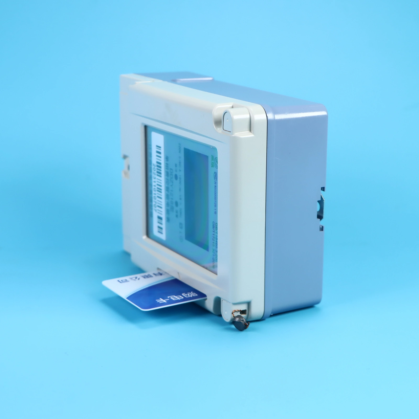
External dimensions
158×112×60(mm)
158×112×60(mm)
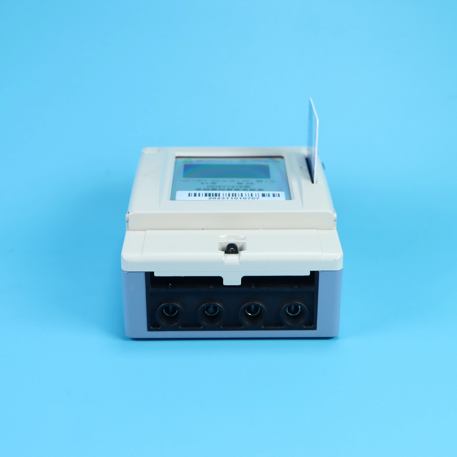
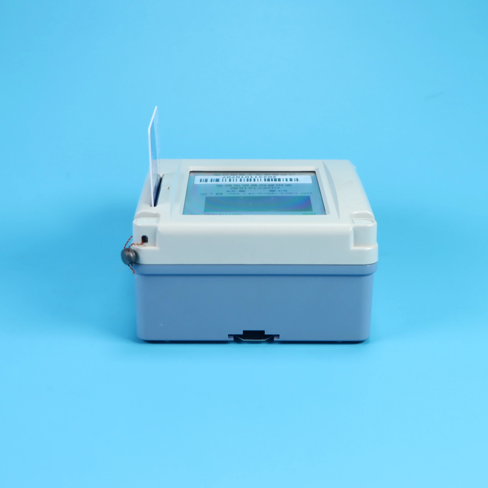
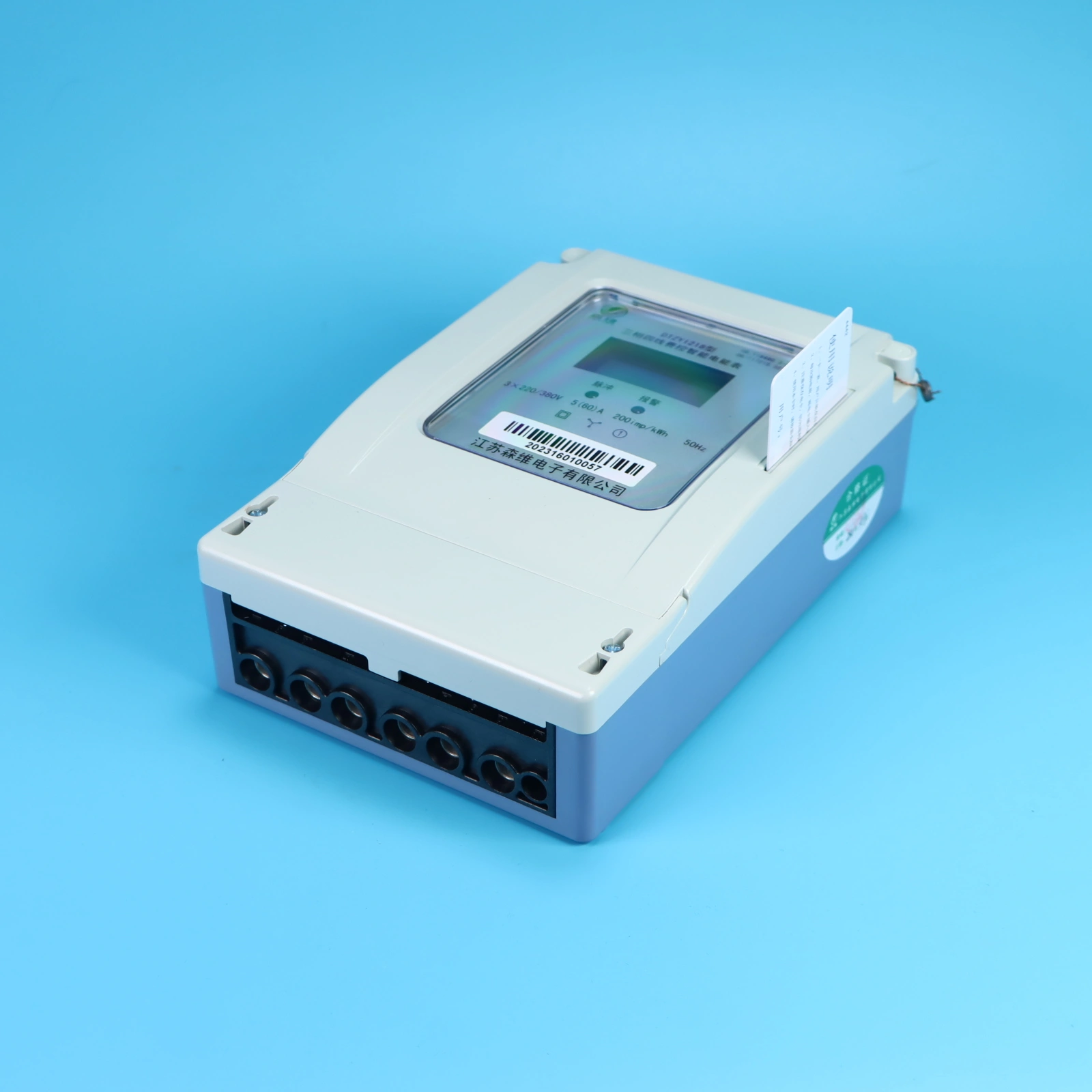
Installation and wiring of electricity meter
The electricity meter shall be installed in a ventilated and dry place to ensure the safety and reliability of installation and use. In places with dirt or possible damage to the electricity meter, the electricity meter shall be protected by a protective cabinet.
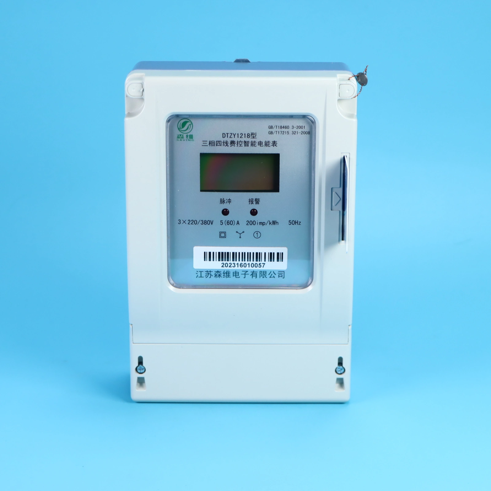
Functional description
Measuring functions
It has the function of measuring combined active power and can store its data.
Remote on/off function
The system can remotely enforce power supply and disconnection functions. When the remaining balance in the users meter falls below zero, it sends a closing command to restore power. If the balance exceeds zero, it issues a disconnection command that triggers immediate power cutoff by the meter.
Automatic power failure function
When the users current remaining power is less than the alarm power, the two words "alarm" on the LCD will flash to remind the user that the current remaining power is insufficient and the power needs to be purchased. When the current remaining power is 0Kwh or the remaining power is less than the automatic power cut-off power, the relay in the electricity meter is disconnected and the users power supply is interrupted.
When the Kwh or the remaining power is less than the automatic power cut, the relay in the electricity meter is disconnected and the users power supply is interrupted.
Display function
The electricity meter in this section can display the following information:
Display the alarm power;
Display the power storage;
Current constant;
Display the mailing address;
Display the remaining power;
Current total electricity.
The number of electricity display is 8 digits, including 2 decimal places.
During the initial power-up cycle of the meter, the displayed information includes: 1) Current consumption; 2) Total electricity consumption; 3) Recharge command response (displaying purchased electricity); 4) Subsequent display of list information in a loop. After completing the initial cycle, the system will sequentially display: 1) Remaining electricity; 2) Total electricity consumption; 3) Recharge command response; 4) Subsequent display of list information in a loop.
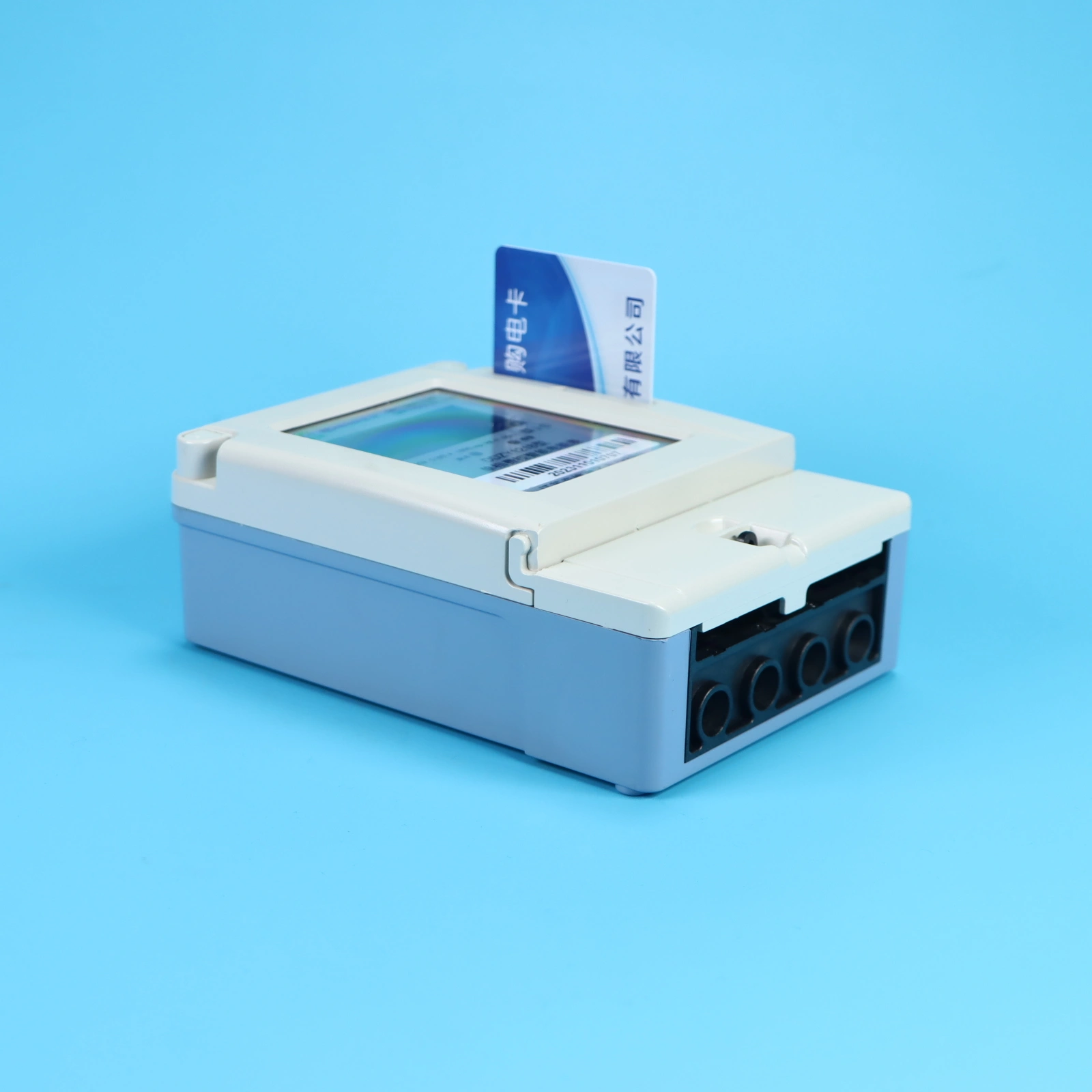
Electricity selling function
The electricity meter can conduct transactions through remote power sales and IC card-based payments. It does not accept erroneous command frames or incorrect purchase count commands. To prevent the power sales system from failing to receive valid data due to communication interruptions – even when
Copyright © 2026 江苏森维电子有限公司 Ltd. All Rights Reserved. POWERED BY WEIMOBTRADE