
Technical Features
Incorporates a high-speed, high-precision AC voltage and current acquisition module, ensuring high sampling accuracy and precise, real-time energy metering;
Capable of time-of-use (TOU) metering for both active and reactive energy, with data storage capabilities; simultaneously features both RS485 and infrared communication functions;
Possesses excellent electromagnetic compatibility (EMC) performance, capable of withstanding interference from high-voltage spikes, strong magnetic fields, strong electrostatic discharges, and lightning surges; also features a robust temperature self-adaptation range;
Powered by a three-phase supply; the energy meter remains fully operational as long as power is present in any single phase;
Low power consumption;
Features a sealed design utilizing waterproof and flame-retardant PVC material; adopts a wall-mounted structure that is compact, lightweight, and easy to install.
Technical Specifications
Accuracy Class: Active Class 1; Reactive Class 2
Rated Frequency: 50 Hz
Starting Current: 0.004 In (Class 1); 0.004 In (Class 2)
Electrical Parameters
|
Normal Operating Voltage |
0.8Un~1.1Un |
|
Limit Operating Voltage |
0.7Un~1.2Un |
|
Voltage Circuit Power Consumption |
≤ 2W and 5VA |
|
Current Circuit Power Consumption |
<1VA |
Climatic Conditions
|
Normal Operating Temperature |
-25℃~+60℃ |
|
Extreme Operating Temperature |
-40℃~+70℃ |
|
Storage and Transport Temperature |
-40℃~+70℃ |
|
Storage and Operating Humidity |
≤85% |
Technical Parameters
|
Display |
LCD |
|
Communication |
RS485 Port: 9600 bps Infrared Interface:9600bps |
Specifications
|
Connection Type |
Voltage Rating |
Current Rating |
Constant(imp/kWh) |
|
Via CTs |
3×220/380 |
3×1.5(6)A |
6400 |
|
Direct Connection |
3×220/380 |
3×5(60)A |
400 |
|
3×10(100)A |
400 |
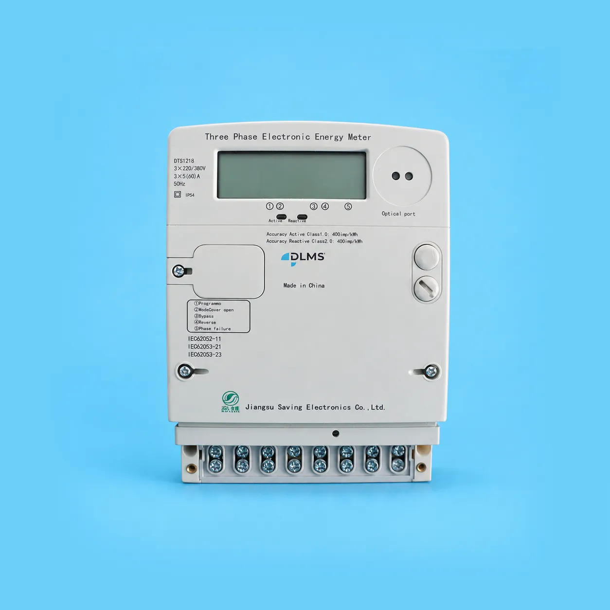
Appearance Description
The meter casing is constructed from ABS and polycarbonate materials; it is recyclable at the end of the meter's service life, thereby complying with relevant environmental regulations. The casing ensures double insulation and meets national standards regarding dust resistance, water resistance, flame retardancy, and general ingress protection. It features an aesthetically pleasing design, a rational structure, and ease of installation.
Installation Instructions
The electricity meter should be installed indoors in a well-ventilated and dry location to ensure safe and reliable operation. In environments prone to contamination or where there is a risk of physical damage to the meter, the device should be housed within a protective cabinet.
The upper section of the meter features a mounting hole for a hanging screw; this should be secured using a PWM4×10 screw. The lower section of the meter contains two mounting holes, which should be secured using PA4×10 or PA4×12 self-tapping screws. Prior to mounting, drill holes into the mounting baseplate according to the installation dimensions illustrated in the diagram below. The baseplate itself must be affixed to a sturdy, fire-resistant, and vibration-resistant surface.
The electricity meter must be wired correctly in strict accordance with the provided wiring diagram. For connections within the terminal block enclosure, the use of copper wires or copper-based connectors is recommended. All screws within the terminal block enclosure must be securely tightened to prevent overheating and potential burnout caused by poor electrical contact or the use of undersized wiring.
Basic Functions
Energy Metering Function
Possesses the capability to meter forward and reverse active energy, and is able to store the corresponding data.
Demand Measurement
a) Measures bidirectional active and reactive maximum demand, as well as time-of-use (TOU) maximum demand—including the date and time of their occurrence—and stores this time-stamped data.
b) Maximum demand measurement employs a sliding window method; both the demand period and the sliding interval are configurable. Factory default settings: Demand Period = 15 minutes; Sliding Interval = 1 minute.
c) In the event of power-up, TOU period transitions, data clearing, clock adjustments, or similar occurrences, the energy meter initiates demand measurement from the current moment in accordance with the configured demand period. Once the initial demand period is completed, maximum demand measurement proceeds according to the specified sliding interval. No maximum demand records are generated during any incomplete demand period.
d) Capable of storing maximum demand data for the past 12 billing cycles.
Key Display
In the cyclic display mode, pressing the "Page Down" button causes the energy meter to enter the key display mode. While in key display mode, pressing a display button again switches the screen to the next display page. Once button activity ceases, the energy meter automatically reverts to the cyclic display mode after a specific interval (the exit delay is configurable within a range of 1 to 255 seconds, with a default setting of 60 seconds). The specific items displayed in key display mode are configurable; the actual display content is configured via the communication port.
There are three distinct sets of key display content available; these can be toggled by long-pressing the page-flipping button.
Power-off Display
In Power-off Display mode, pressing the Display button causes the energy meter to enter Power-off Button Display mode. Pressing the Display button again switches the display to the next page. Once button activity ceases, the energy meter automatically reverts to Power-off mode after a specific duration (default: 20 seconds). While in Power-off Button Display mode, pressing the button again displays the content of the next page.
Up to three settlement points can be configured per month, and historical data for the most recent 12 settlements can be stored. Historical data for the two most recent settlement points can be
Copyright © 2026 江苏森维电子有限公司 Ltd. All Rights Reserved. POWERED BY WEIMOBTRADE