Technical Features
Incorporates a high-speed, high-precision AC voltage and current acquisition module, ensuring high sampling accuracy and precise, real-time energy metering;
Capable of time-of-use (TOU) metering for both active and reactive energy, with data storage capabilities; simultaneously features both RS485 and infrared communication functions;
Exhibits excellent electromagnetic compatibility, capable of withstanding interference from high-voltage spikes, strong magnetic fields, strong electrostatic discharges, and lightning surges; also possesses a robust temperature self-adaptation range;
Powered by a three-phase supply; the energy meter remains fully operational as long as power is present in any single phase;
Features a built-in high-precision clock chip and a backup battery to sustain clock operation during power outages, ensuring the clock remains functional for up to 10 years without external power;
Low power consumption;
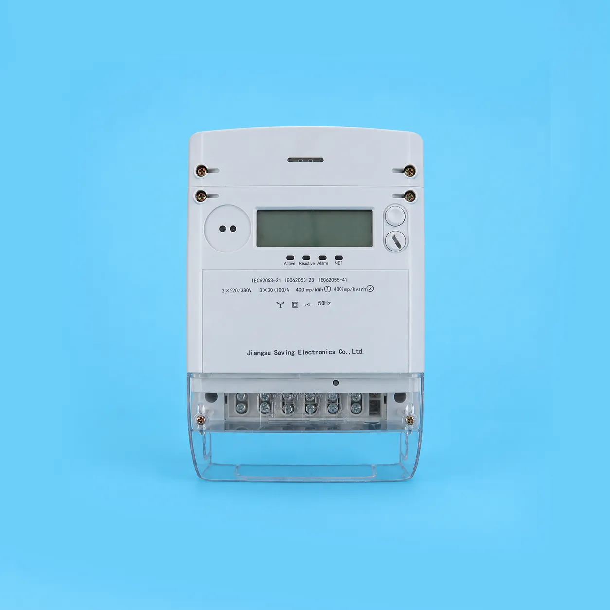
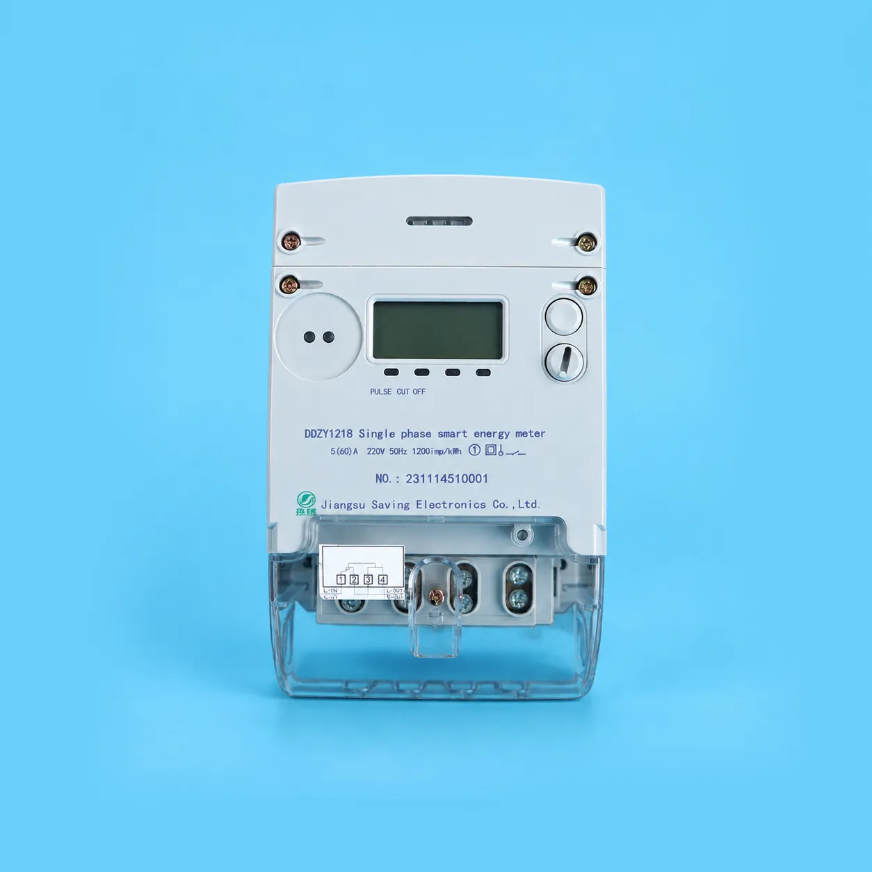
Features a sealed design utilizing waterproof and flame-retardant PVC materials; adopts a wall-mounted structure that is compact, lightweight, and easy to install.
Working Principle
During operation, the voltage and current signals from the A, B, and C phases are sampled via dedicated sampling circuits and then transmitted to the metering chip for processing. The CPU subsequently routes the processed data to various output units—such as the display module and communication interface—as required.
Specification
|
Model
|
Accuracy
|
Connection Type
|
Voltage Rating (V)
|
Current Rating (A)
|
Constant (imp/kWh)
|
|
DSZY1218
|
Active: Class B/C; Reactive: Class 2
|
Via CT
|
3×100
|
0.015-0.075(6)
|
20000
|
|
DTZY1218
|
Active Power: Class B/C; Reactive Power: Class 2
|
Via Current Transformer
|
3×57.7/100
|
0.015-0.075(6)
|
20000
|
|
Via Current Transformer
|
3×220/380
|
0.015-0.075(6)
|
6400
|
|
Active Power: Class B; Reactive Power: Class 2
|
Direct Connection
|
3×220/380
|
0.2-0.5(60)
|
400
|
|
0.4-1(100)
|
400
|
The specifications listed above represent our company's standard stock configurations; however, we are able to modify these specifications to meet specific user requirements.
Technical Specifications
Power Consumption (under reference conditions)
Per voltage circuit phase: ≤ 1.5 W, 6 VA; Per current circuit phase: Base current (less than 10 A) ≤ 0.2 VA; Base current (greater than 10 A) ≤ 0.4 VA.
Timekeeping Accuracy:Daily timekeeping error ≤ 0.5 s/d (at 23°C); Error ≤ 1.0 s/d (within the range of -30°C to +70°C).
Voltage Range (assuming no phase loss)
Specified Operating Range: 0.9 Un – 1.1 Un
Extended Operating Range: 0.8 Un – 1.15 Un
Limit Operating Range: 0.0 Un – 1.15 Un
Reference Frequency:50 Hz
Data Backup Battery
Voltage: 3.6 V; Capacity: ≥ 1.2 Ah; Lifespan: ≥ 10 years
Retention period for settlement data after power failure: ≥ 10 years; Retention period for other data: ≥ 5 years.
Battery for Meter Reading During Power Outage
Voltage: 6 V; Capacity: ≥ 1200 mAh
Environmental Conditions
a) Reference Temperature and Reference Humidity
Reference Temperature: 23°C; Reference Humidity: 45% – 75% RH
b) Temperature Range
Normal Operating Temperature: -25°C – 55°C
Limit Operating Temperature: -40°C – 70°C
Transport and Storage Temperature: -40°C – 70°C
c) Relative Humidity Range
Annual average relative humidity: < 75%
Relative humidity for 30 days (naturally distributed throughout the year): ≤ 95%
Relative humidity occurring occasionally on other days: ≤ 85%
Mechanical Parameters
Dimensions: 160 mm × 253 mm × 73 mm (Length × Width × Depth)
Weight: Approx: kg
Appearance Description and Installation
Appearance Description
The enclosure is constructed from ABS and polycarbonate materials; it is recyclable at the end of the meter's service life and complies with relevant environmental regulations. The meter casing ensures double insulation and meets national standards regarding dust resistance, water resistance, flame retardancy, and general protection. It features an aesthetically pleasing design, a rational structure, and convenient installation.
Upon opening the small cover located at the top, a battery slot can be found in the upper-left corner, housing a 3.6V lithium battery. During installation, please pay close attention to the correct polarity (positive and negative) of the battery. Additionally, a dedicated module compartment is provided to accommodate wireless communication modules, such as 4G, NB-IoT, or Wi-Fi.
Installation Instructions
The electricity meter should be installed indoors in a well-ventilated and dry location to ensure safe and reliable operation. In environments characterized by excessive contamination or conditions that could potentially damage the meter, the device should be housed within a protective cabinet.
The upper section of the meter features a mounting hole designed for a hook screw; secure this point using a PWM4×10 screw. The lower section of the meter contains two mounting holes; secure these points using PA4×10 or PA4×12 self-tapping screws. Prior to mounting, drill the necessary holes in the mounting baseplate according to the installation dimensions illustrated in the diagram below. The baseplate itself must be securely fixed to a sturdy, fire-resistant, and vibration-resistant surface.
The electricity meter must be wired correctly in strict accordance with the provided wiring diagram. It is recommended to use copper wires or copper terminals for the incoming connections within the terminal block compartment. All screws within the terminal block must be securely tightened to prevent potential burnout caused by poor contact or overheating resulting from the use of undersized wires.
Main Functions
Energy Metering
a) Features metering functions for forward active energy, reverse active energy, and four-quadrant reactive energy; based on these values, combined active energy and combined reactive energy can be configured.
b) Features a Time-of-Use (TOU) metering function, allowing for the separate accumulation and storage of total, peak, shoulder, off-peak, and valley active and reactive energy values according to corresponding time periods.
c) Features a function for metering phase-specific active energy.
Demand Measurement
a) Measures bidirectional maximum demand, maximum demand by time period, and the date and time at which these values occurred, storing the data with corresponding timestamps.
b) Maximum demand measurement employs a sliding window method; both the demand interval and the sliding window duration are configurable. Factory default values: Demand interval = 15 minutes; Sliding window duration = 1 minute.
c) In the event of power-up on the voltage circuit, time period transitions, data resets, clock adjustments, or similar occurrences, the energy meter initiates demand measurement from the current moment in accordance with the configured demand interval. Once the first complete demand interval has elapsed, maximum demand measurement begins based on the sliding window interval. No maximum demand records are generated during any incomplete demand interval.
d) Capable of storing maximum demand data for the past 12 billing cycles.
Display Functions
The display content consists of two components: the primary numerical value and an auxiliary display comprising codes or Chinese characters. The auxiliary codes and characters serve to identify the specific displayed item and indicate the corresponding unit of measurement.
The display supports two modes: automatic cyclic display and on-demand display via key press. The specific items included in the display sequence can be configured according to requirements. The cycle duration for the automatic display sequence can be set within a range of 5 to 20 seconds, with a default value of 5 seconds.
Features an anomaly indication function. When the energy meter detects operational anomalies (such as voltage loss, current loss, current imbalance, phase loss, reverse active power flow, reverse voltage phase sequence, low battery voltage, etc.), it displays a corresponding symbol to alert the user.
Features a backlight display function. While the energy meter is in an operational state, the backlight can be activated via triggers such as key presses or infrared signals; the backlight automatically switches off after two full cycles of the automatic display sequence.
Clock, Time-of-Use Periods, and Tariff Functions