
Technical Features
Incorporates a high-speed, high-precision AC voltage and current acquisition module, ensuring high sampling accuracy and precise, real-time energy metering;
Capable of time-of-use (TOU) metering for both active and reactive energy, with data storage capabilities; simultaneously features both RS485 and infrared communication functions;
Exhibits excellent electromagnetic compatibility, capable of withstanding interference from high-voltage spikes, strong magnetic fields, intense static electricity, and lightning surges; also features a robust temperature self-adaptation range;
Powered by a three-phase supply; the energy meter remains fully operational as long as power is present in any single phase;
Features a built-in high-precision clock chip and a backup battery to sustain clock operation during power outages, ensuring the clock remains functional for up to 10 years under power-loss conditions;
Low power consumption;
Features a sealed design utilizing waterproof and flame-retardant PVC materials; adopts a wall-mounted structure that is compact in size and easy to install.
Working Principle
During operation, the voltages and currents of the A, B, and C phases are sampled by a dedicated sampling circuit and subsequently transmitted to a metering chip for processing. The CPU then routes the processed data, as required, to various data output units—such as the display module and the communication module.
Specifications
|
DTZY1218-D |
Active: Class B/C; Reactive: Class 2 |
Via CT |
3×57.7/100 |
0.015-0.075(6) |
20000 |
|
Via CT |
3×220/380 |
0.015-0.075(6) |
6400 | ||
|
Active: Class B; Reactive: Class 2 | Direct Connection |
3×220/380 |
0.2-0.5(60) |
400 | |
|
0.4-1(100) |
400 | ||||
|
DSZY1218 |
Active: Class B/C; Reactive: Class 2 |
Via CT |
3×100V |
0.015-0.075(6) |
20000 |
The specifications listed above represent only our company's standard stock sizes; we are able to modify these specifications to meet the specific requirements of our customers.
Technical Specifications
Power Consumption (under reference conditions)
Per voltage circuit phase: ≤ 1.5 W, 6 VA; Per current circuit phase: Base current (less than 10 A) ≤ 0.2 VA; Base current (greater than 10 A) ≤ 0.4 VA.
Timekeeping Accuracy
Daily timekeeping error ≤ 0.5 s/d (at 23°C); Error ≤ 1.0 s/d (within the range of -30°C to +70°C).
Voltage Range (in the absence of phase loss)
Specified Operating Range: 0.9 Un – 1.1 Un
Extended Operating Range: 0.8 Un – 1.15 Un
Limit Operating Range: 0.7 Un – 1.15 Un
Reference Frequency: 50 Hz
Data Backup Battery
Voltage: 3.6 V; Capacity: ≥ 1.2 Ah; Lifespan: ≥ 10 years
Retention period for billing data after power failure: ≥ 10 years; Retention period for other data: ≥ 5 years.
Battery for Meter Reading During Power Outage
Voltage: 6V; Capacity: ≥1200mAh
Environmental Conditions
a) Reference Temperature and Reference Humidity
Reference Temperature: 23°C; Reference Humidity: 45%–75% RH
b) Temperature Range
Normal Operating Temperature: -25°C to 55°C
Extreme Operating Temperature: -40°C to 70°C
Transport and Storage Temperature: -40°C to 70°C
c) Relative Humidity Range
Annual average relative humidity: <75%
Relative humidity for 30 days (naturally distributed throughout the year): ≤95%
Relative humidity occurring occasionally on other days: ≤85%
Mechanical Parameters
Dimensions: 290mm × 170mm × 85mm (Length × Width × Depth)
Weight: Approx. 2.5kg
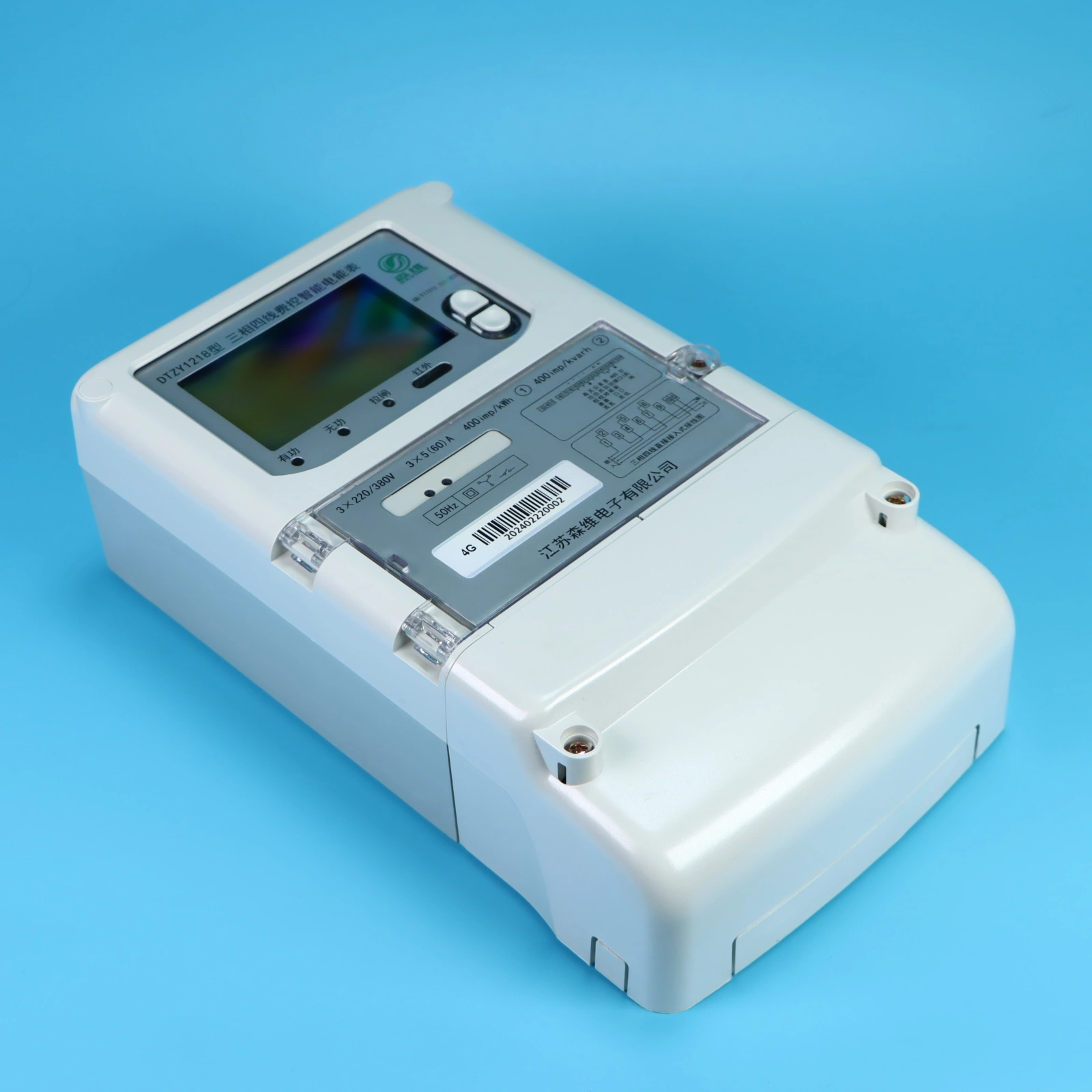
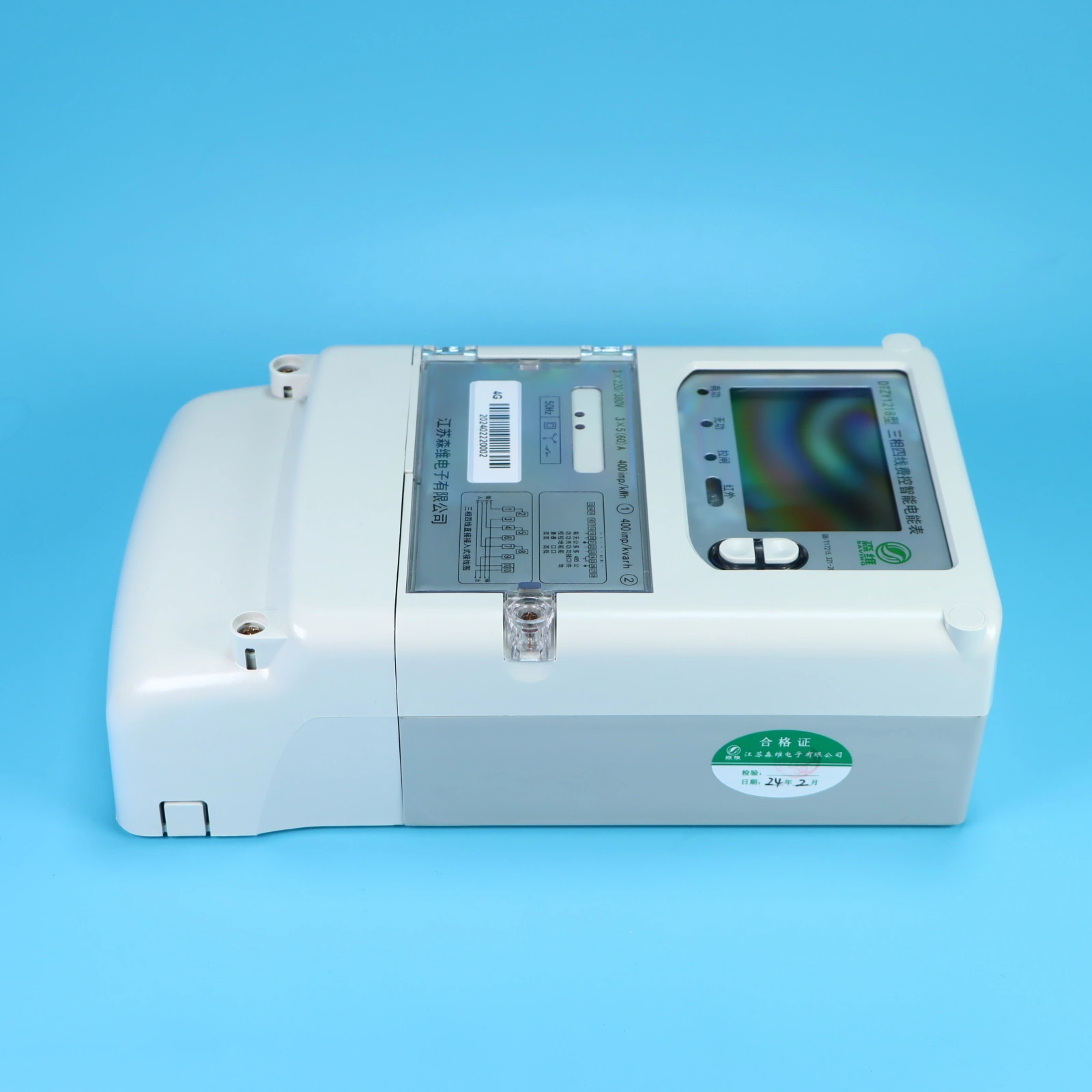
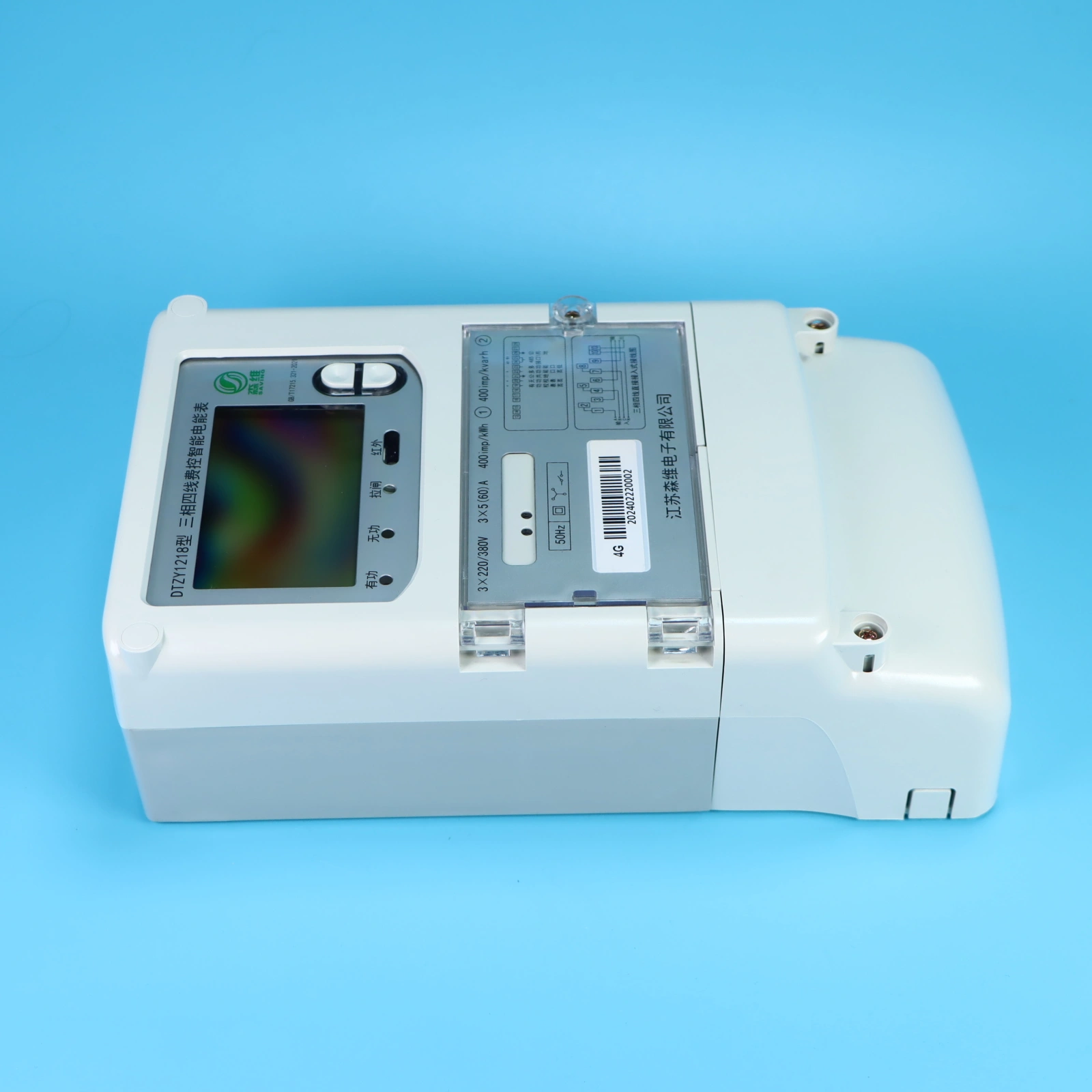
Appearance Description and Installation
Appearance Description
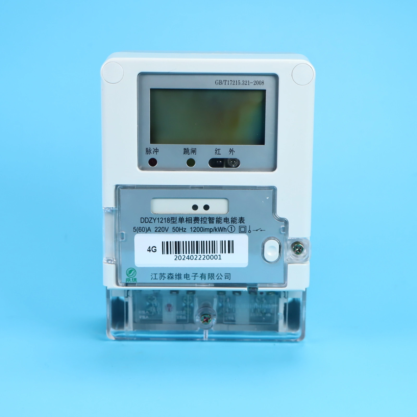
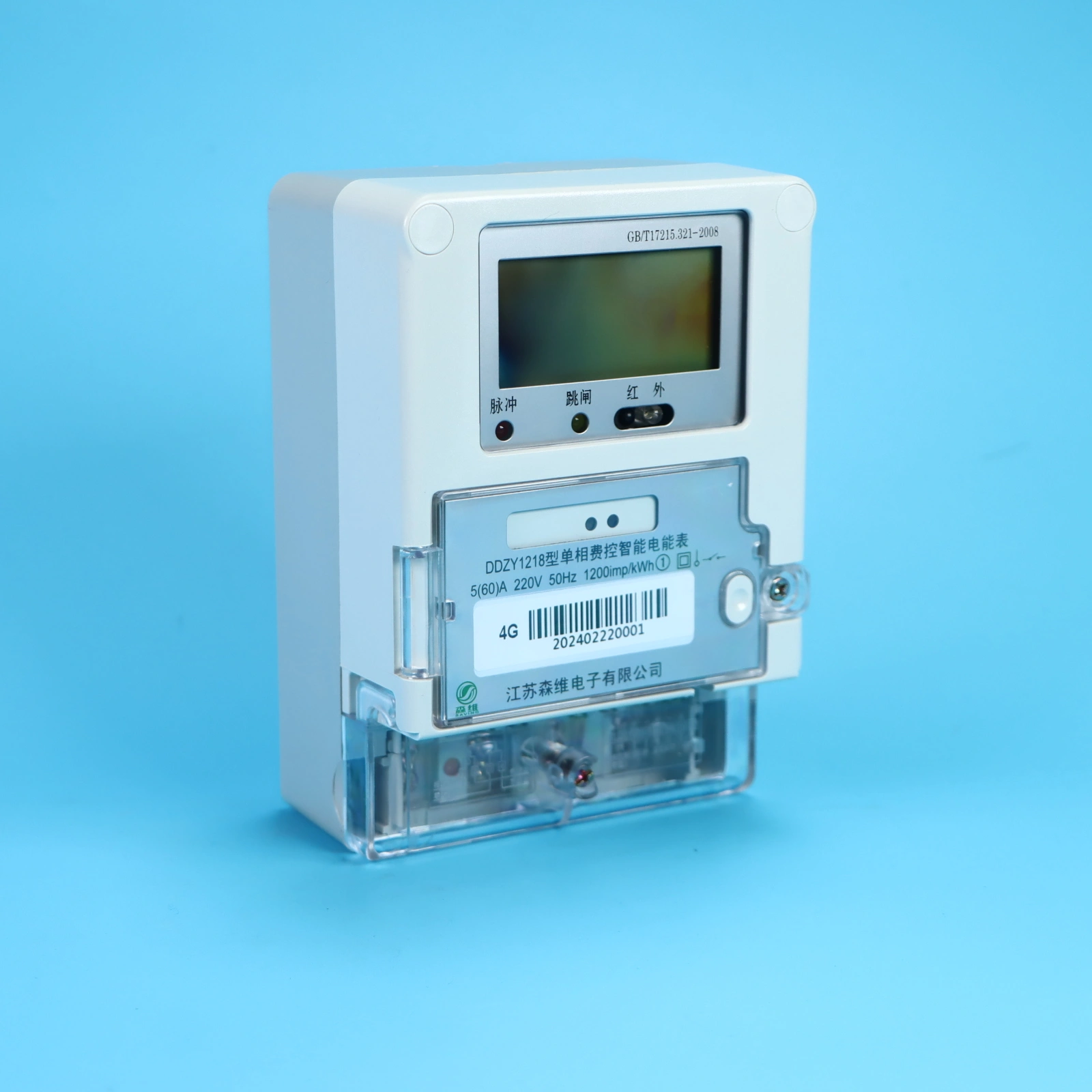
The enclosure is constructed from ABS and polycarbonate materials; it is recyclable at the end of the meter's service life and complies with relevant environmental regulations. The meter casing ensures double insulation and meets national standards regarding dust protection, water resistance, flame retardancy, and general ingress protection. It features an aesthetically pleasing design, a rational structure, and ease of installation.
Upon opening the transparent flip cover, a small access panel can be found in the upper-right corner. Opening this panel reveals a battery slot containing a 6V lithium battery, which is used to power the meter for reading purposes during a power outage (the meter's internal circuitry already contains a soldered 3.6V clock battery to maintain internal data integrity and keep the real-time clock running). When installing the battery, please pay close attention to the correct orientation of the positive and negative terminals.
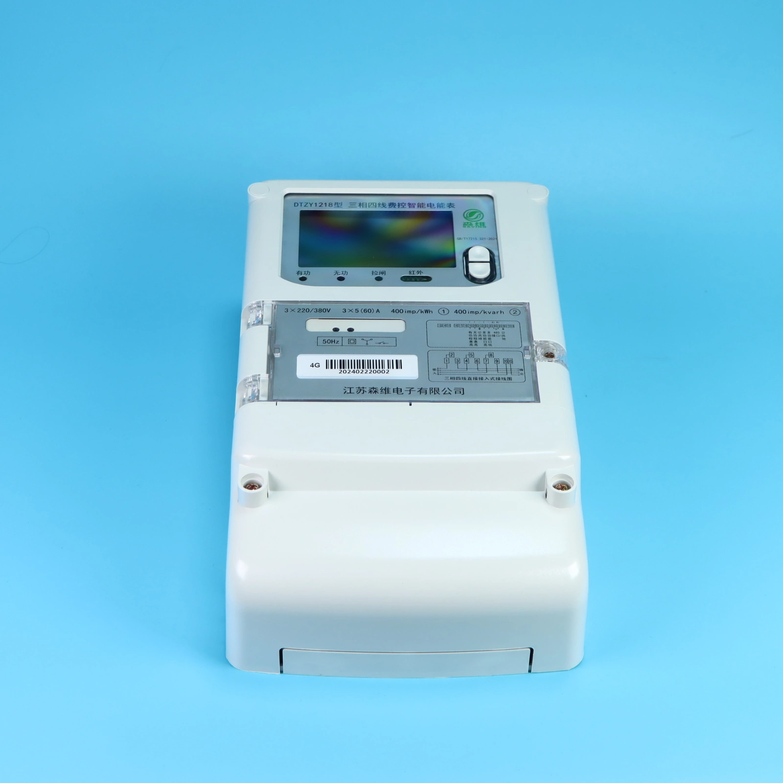
Installation Instructions
The electricity meter should be installed indoors in a well-ventilated and dry location to ensure safe and reliable operation. In environments prone to contamination or where there is a risk of physical damage to the meter, the device should be housed within a protective cabinet.
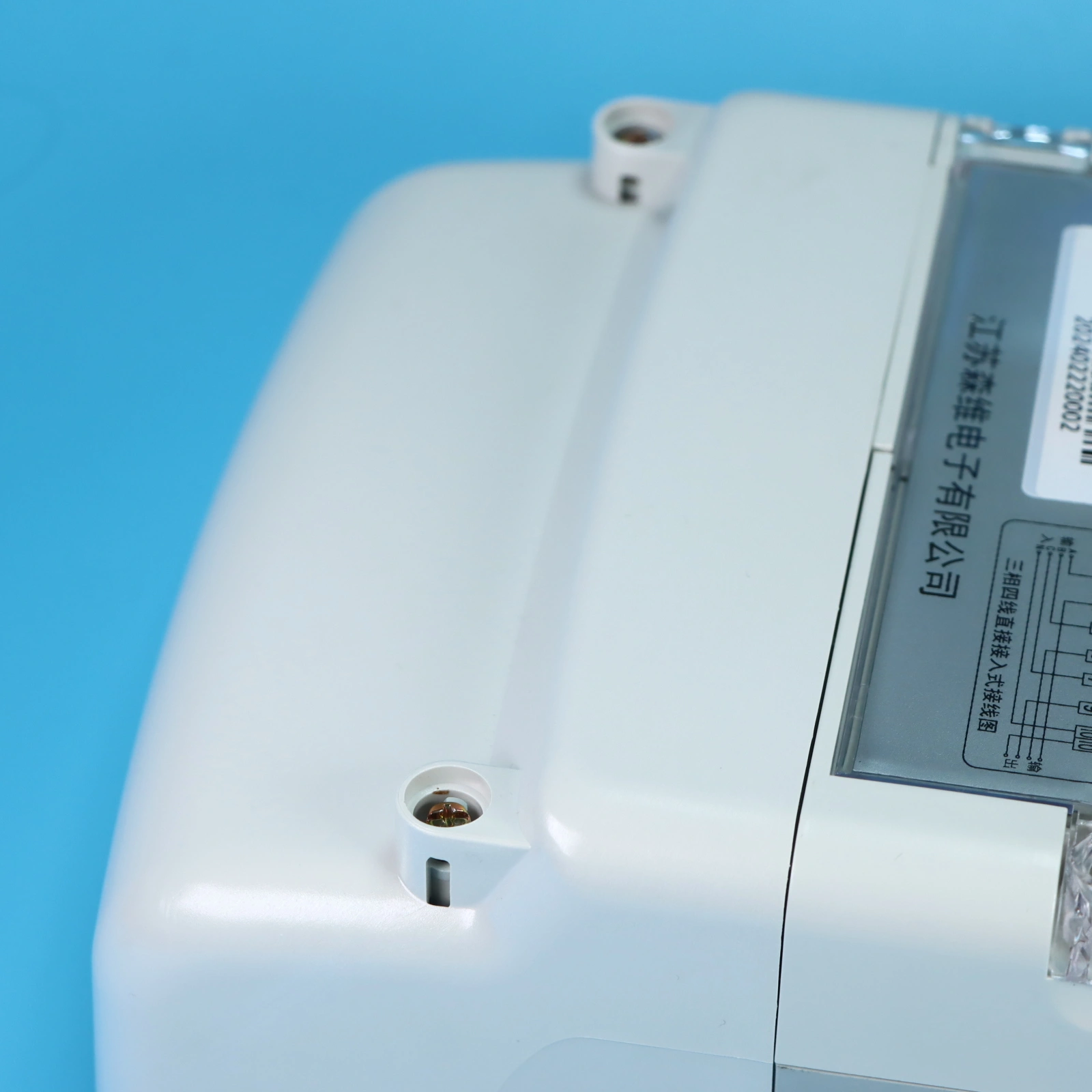
The upper section of the electricity meter features a mounting hole for a hook screw; this should be secured using a PWM4×10 screw. The lower section of the meter contains two mounting holes, which should be secured using PA4×10 or PA4×12 self-tapping screws. Drill holes in the mounting plate in advance, in accordance with the installation dimensions shown in the accompanying diagram. The base must be securely fixed to a sturdy, fire-resistant, and vibration-resistant surface.
The electricity meter must be wired correctly, strictly following the provided wiring diagram. It is recommended to use copper wires or copper terminals for the incoming connections to the terminal box. The screws within the terminal box must be tightened securely to prevent burnout caused by poor contact or overheating due to the use of wires that are too thin.
Main Functions
Energy Metering
a) Features metering functions for forward active energy, reverse active energy, and four-quadrant reactive energy; based on these measurements, combined active energy and combined reactive energy can be configured.
b) Features Time-of-Use (ToU) metering functionality, allowing for the separate accumulation and storage of total, peak, shoulder, off-peak, and valley active and reactive energy values according to corresponding time periods.
c) Features the capability to meter active energy on a per-phase basis.
Demand Measurement
a) Measures bidirectional maximum demand, maximum demand per time period, and the date and time of their occurrence, storing this data with associated timestamps.
b) Maximum demand measurement employs a sliding window method; both the demand period and the sliding interval are configurable. Factory default values: Demand Period = 15 minutes; Sliding Interval = 1 minute.
c) In the event of power-up on the voltage lines, time period transitions, data resets, clock adjustments, or similar events, the energy meter initiates demand measurement from the current moment in accordance with the configured demand period. Once the first complete demand period has elapsed, maximum demand measurement commences based on the specified sliding interval. No maximum demand records are generated during any incomplete demand period.
d) Capable of storing maximum demand data for the past 12 billing cycles.
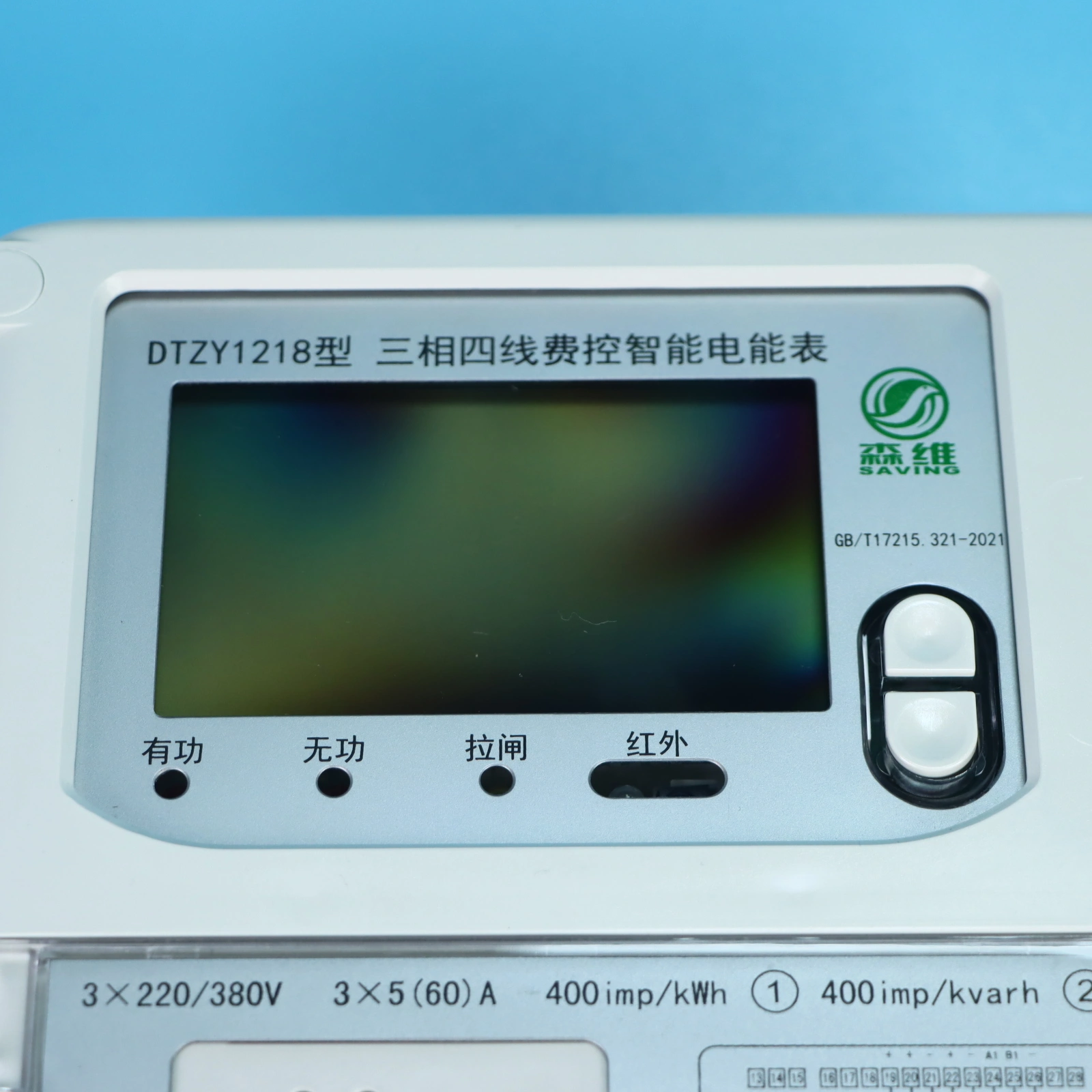
Display Functions
The display content consists of two components: the primary numerical value and an auxiliary display comprising codes or Chinese characters. These auxiliary codes and characters serve to identify the specific displayed item and indicate the units of the numerical value.
The display mode can be configured for either automatic cyclic display or manual button-triggered display; the specific items included in the display sequence can be customized according to requirements. The cycle duration for the automatic display sequence can be set within a range of 5 to 20 seconds, with a default setting of 5 seconds.
Includes an anomaly indication function. Should the energy meter encounter operational anomalies (such as voltage loss, current loss, current imbalance, phase loss, reverse active power flow, reverse voltage phase sequence, low battery voltage, etc.), a corresponding symbol will be displayed to provide an alert.
During operation, the meter's backlight will illuminate to serve as an alarm indicator in the event of voltage loss, reverse phase sequence, overload, reverse power flow (except for bidirectional meters), or low clock battery voltage.
Features a backlight display function. When the energy meter is in operational mode, its backlight can be activated via triggers such as button presses or infrared signals; the backlight will automatically switch off after two complete cycles of the display rotation sequence.
Clock, Time-of-Use Periods, and Tariff Functions
The meter utilizes a built-in hardware clock circuit featuring temperature compensation capabilities, with an internal clock terminal output frequency of 1 Hz. Rigorous protective measures have been implemented within the meter to ensure the accuracy of the clock, guaranteeing that the daily time error remains less than 0.5 seconds across the meter's entire operating temperature range (from -25°C to +55°C).
Number of Tariffs: This parameter indicates the maximum number of distinct tariff rates that the energy meter can switch between. Users may configure this setting according to their specific requirements. The configured number of tariffs must fall within the range of 0 to 12 (inclusive); any other input values will result in an "abnormal response" error.
Daily Time-of-Use Schedule: The 1 to 14 daily time periods can be combined with 1 to 12 specific tariff rates—as required—to create a "Daily Time-of-Use Schedule" (also referred to as "Seasonal Tariffs"). Up to 8 distinct schedules can be configured. Additionally, a "backup schedule" and its corresponding activation time can be pre-set to facilitate the simultaneous modification of
Copyright © 2026 江苏森维电子有限公司 Ltd. All Rights Reserved. POWERED BY WEIMOBTRADE