Energy Efficiency Monitoring and Management System Solution
Smart energy efficiency monitoring and management system with real-time power consumption monitoring, energy data analysis, intelligent metering, and remote management to improve energy efficiency and reduce operating costs.
2026/09/10
Reading volume: 2
Case Details
Chinese economic development has entered a "new normal," characterized by significantly accelerated industrial restructuring, slowing growth in energy consumption, and a gradual decline in resource-intensive, high-energy-consuming, and high-emission industries. However, as industrialization and urbanization accelerate and consumption patterns evolve, energy and environmental issues have become bottlenecks for economic growth, making the tasks of energy conservation and emission reduction particularly arduous. Consequently, the government is playing a leading role—utilizing administrative measures—to accelerate the deployment of online energy consumption monitoring systems for energy-using entities and to improve energy metering frameworks. Driven by societal demand and strong government advocacy, the sectors for electrical energy management systems and broader energy management systems have expanded rapidly. These systems are undergoing continuous technological innovation, broadening their scope of application, and incorporating increasingly comprehensive intelligent features.
Most energy systems in complex buildings currently achieve real-time monitoring of various energy sources, including water, electricity, gas, and thermal energy. However, the supply, consumption, and storage systems within these buildings operate independently of one another; this lack of coordination creates "information islands." Furthermore, integration with various automated control systems is hindered by incompatible communication protocols, preventing seamless connectivity and making coordinated control and management difficult. Current energy management in complex buildings faces the following issues:
(1) Energy-consuming equipment lacks effective process monitoring, making it impossible to preemptively identify or eliminate safety hazards or to adequately handle system faults and anomalies. Operational management lacks systematic maintenance support and diagnostic measures; energy optimization strategies lack scientific grounding and feasibility, resulting in suboptimal implementation outcomes.
(2) The functionality of existing energy management systems in complex buildings is largely limited to "energy consumption monitoring." These systems collect consumption data but fail to capture other influencing factors—such as indoor and outdoor temperatures, lighting levels, and HVAC operating parameters. This limits the system's overall analytical capability, making it difficult to quickly pinpoint energy inefficiencies or conduct effective energy-efficiency assessments, thereby preventing the system from fulfilling its "management" function.
(3) The low level of energy management in complex buildings results in poor energy efficiency. Regarding the practical use of comprehensive building energy management systems, the limited proficiency of operational personnel—who are often capable of performing only basic start/stop operations and routine maintenance—leads to a scenario where high-efficiency equipment is installed but operated using low-level strategies, ultimately resulting in poor overall energy efficiency.
(4) Inability to interact with the main power grid. None of the comprehensive building energy management systems account for interaction with the main grid; with the exception of a few individual devices or modules that support automated demand response standards, neither domestic nor imported energy control systems for such buildings possess similar interactive capabilities.
Major Energy-Consuming Systems and Equipment in Comprehensive Buildings
(1) Power supply system: Supplied by external distribution lines or on-site rooftop photovoltaic arrays. External high-voltage power requires step-down transformation for use. Aside from the high-voltage equipment itself, major energy-consuming systems and devices include HVAC systems, lighting, elevators, fans, water supply pumps, office power outlets, and electric vehicle charging facilities.
(2) Water supply system: Supplied by the municipal water network; internally, it is divided into systems for domestic water, fire-fighting water, HVAC make-up water, and landscape water.
(3) Gas supply system: Supplied by the external gas network. Gas costs account for approximately 10% of the total energy expenditure of a comprehensive building; the primary gas-consuming equipment within the building consists of gas boilers and kitchen cooking appliances.
(4) Heating system: Jiangsu is not located in a region subject to mandatory state-provided heating; therefore, winter heating for comprehensive buildings is typically supplied by on-site boiler rooms or heat-pump-based HVAC units.
(5) HVAC system: This system accounts for approximately 50% of the building's total energy consumption. It converts energy sources—such as electricity, natural gas, and steam—into cooling and heating sources for climate control, with electrically powered systems predominating. HVAC systems are categorized into water-cooled central air conditioning, multi-split systems, and split-system units. Water-cooled central air conditioning equipment includes the main chiller unit, chilled water pumps, cooling towers, boilers, and terminal units.
(6) Lighting system: Lighting accounts for approximately 15% of the building's total energy consumption. The lighting system equipment primarily includes electrodeless lamps, incandescent lamps, tungsten-halogen lamps, fluorescent lamps, metal-halide lamps, high-pressure sodium lamps, LED lamps, and xenon lamps, as well as downstream equipment connected to sockets.
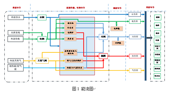
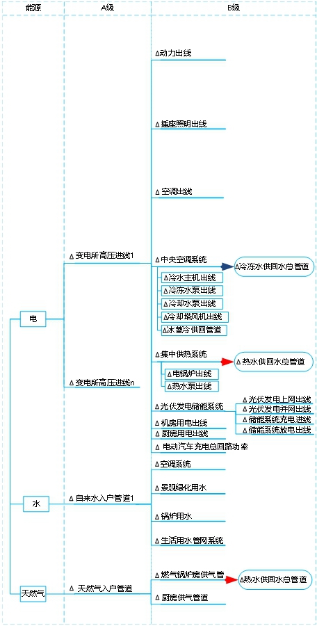
The energy flow diagram for the comprehensive building is shown in the figure below.
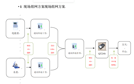
Senwei Electronic Energy Efficiency Monitoring System is divided into four layers. The first layer is the equipment layer, including: power instruments, microcomputer relay protection, photovoltaic inverters, smart switches, fault and wave recording equipment, temperature inspection equipment, DC panels, etc.
The second layer is the collection layer. Through the wireless communication terminal downlink table, the devices in the area collect and transmit data through communication interfaces and protocols, and transmit data to the upper layer through standard interfaces.
The third layer is the transmission layer. Through the wireless communication terminal uplink table, the collection equipment in each area is transmitted through the network to realize data transmission. Common ones include star network, ring network, etc. The link media include twisted pair and optical fiber. Twisted pair can only form a regional network within 200 meters, while GPRS is not limited by distance and can form complex and long-distance transmission layer network media.
The fourth layer is the display layer, which provides graphical presentation effects through monitoring software to graphically display system operating data. In addition to display, it also provides fault information collection, fault reproduction, historical data, waveform analysis, operation logs, operation management and other functions.
Technical Specifications for Energy Efficiency Monitoring Terminals
1.1 Overview
The power energy efficiency monitoring terminal is primarily designed for monitoring three-phase AC energy consumption. It offers optional RS485 and wireless communication capabilities, facilitating electricity usage monitoring, automated meter reading, and remote management. The product features high accuracy, a compact footprint, and ease of installation. It can be flexibly installed within power distribution cabinets to enable sub-metering, statistical analysis, and monitoring of electricity consumption across different zones and load types.
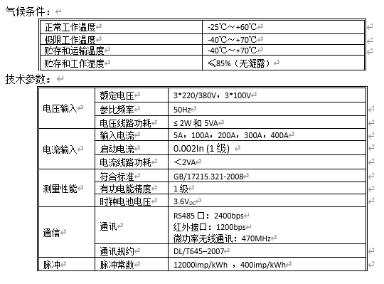
1.2 Technical Specifications
Physical Description and Installation
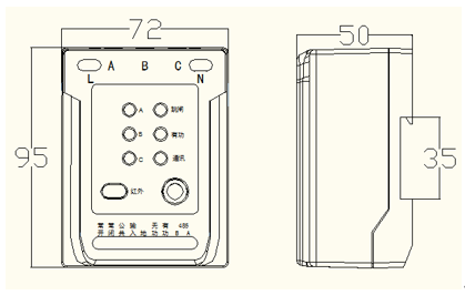
2.1 Outline Drawing
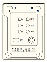
Description of the Power Energy Efficiency Monitoring Terminal Outline Drawing
2.1.1 LED Indicators
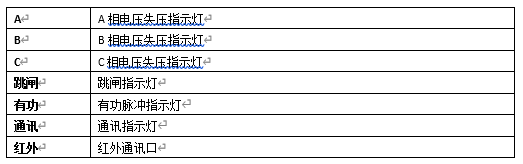
API Description:
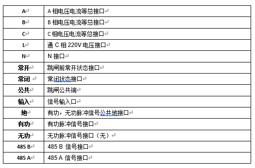
2.2 Installation and Wiring of the Power Energy Efficiency Monitoring Terminal
2.2.1 The power energy efficiency monitoring terminal shall be installed in a well-ventilated, dry indoor location to ensure safe and reliable operation, particularly in areas subject to contamination or conditions that could damage the terminal.
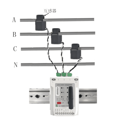
Installation and Wiring: Clip the three split-core sensors (A, B, and C) onto the corresponding Phase A, B, and C cables. Simultaneously, use the three-phase voltage piercing clamps to pierce the cables and draw power. Finally, mount the energy efficiency monitoring terminal onto a nearby DIN rail to complete the installation.
2.2.2 Dimensions: 72 × 95 × 50 mm
2.2.3 The electric energy efficiency monitoring terminal shall be wired correctly in accordance with the wiring diagram.
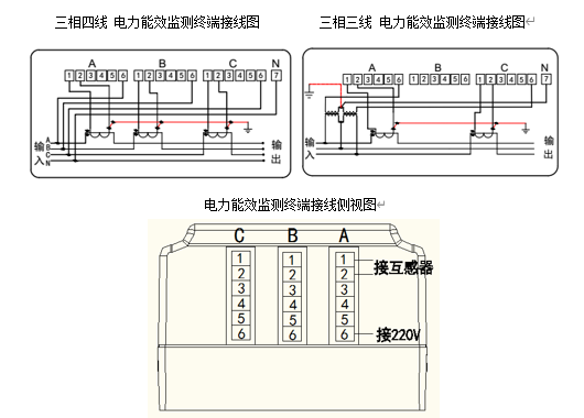
Wiring Diagram and Interface Description:
Current Wiring Instructions: Install the current transformers for phases A, B, and C according to the specified input/output direction (refer to the arrow direction on the transformers).
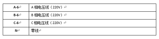
Basic Functions
3.1 Electrical Energy Measurement Function
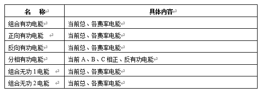
3.2 Measurement Functions
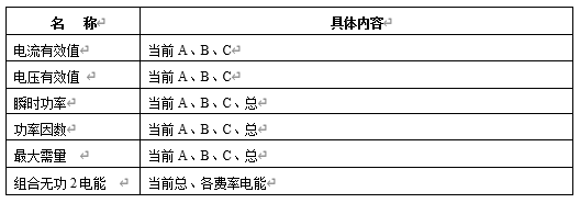
3.3 Tariff and Time-of-Use (TOU) Functions
The meter supports two sets of tariff/time-period schedules, with automatic switching at preset times; each schedule supports 4 tariff rates and 8 time periods.
Equipped with a calendar and clock, the system allows for the configuration of two seasonal zones per year and the arbitrary programming of eight time periods within a 24-hour cycle; the minimum time-period interval is 15 minutes, and time periods can span across midnight.
Supports modification of seasonal zone and time-period schedules via infrared and RS485 communication interfaces, incorporating security measures to prevent unauthorized operation.
3.4 Communication Functions
The meter supports communication via RS485, infrared, and wireless interfaces, enabling simultaneous, interference-free communication across all three channels. The RS485 port supports full functionality, including meter reading and configuration, with a communication rate of 2400 bps; the infrared port operates at 1200 bps. Low-power wireless communication utilizes an SPI bus interface and operates at a frequency of 470 MHz.
The system software comprises modules for login management, record management, daily operations management, query and statistics, and emergency handling (refer to the functional module diagram for details). Each module performs the following functions.
System data acquisition scheme:
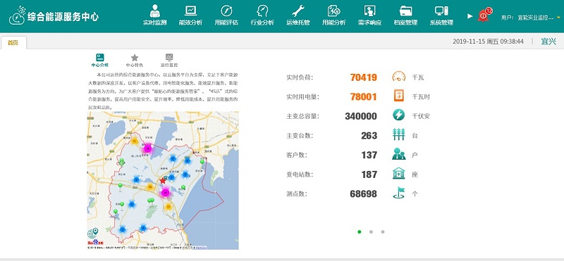
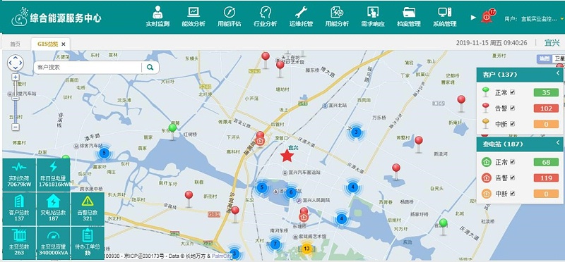
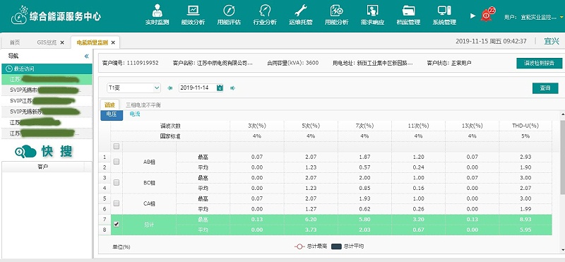
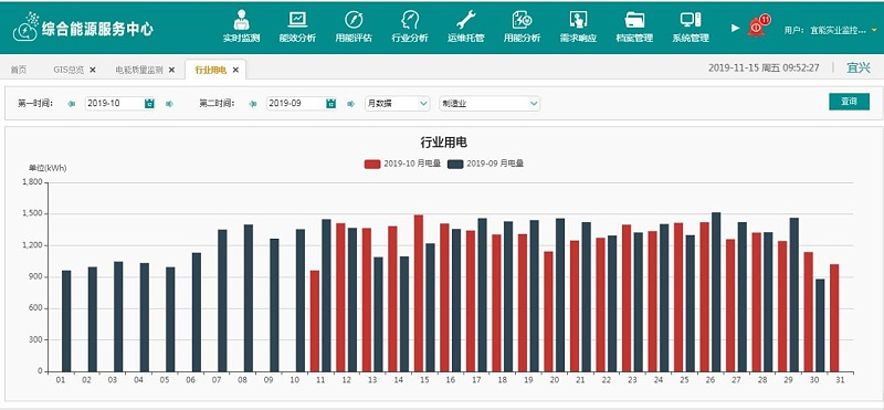
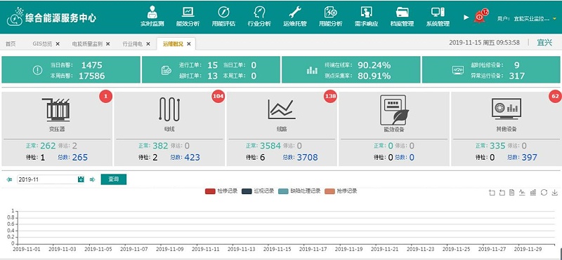
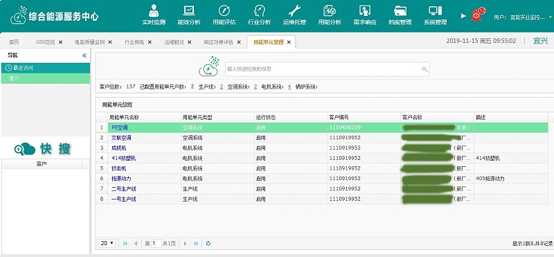
Standard system main interface:
System Menu
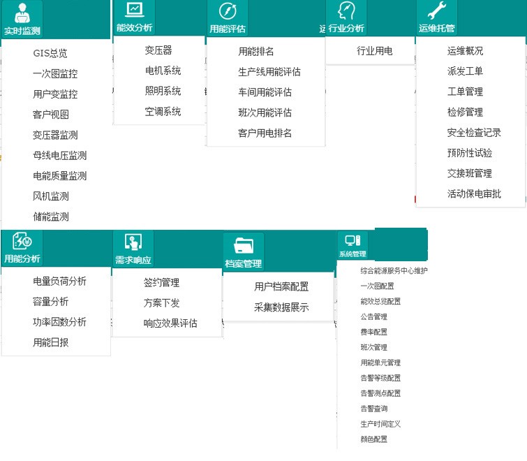
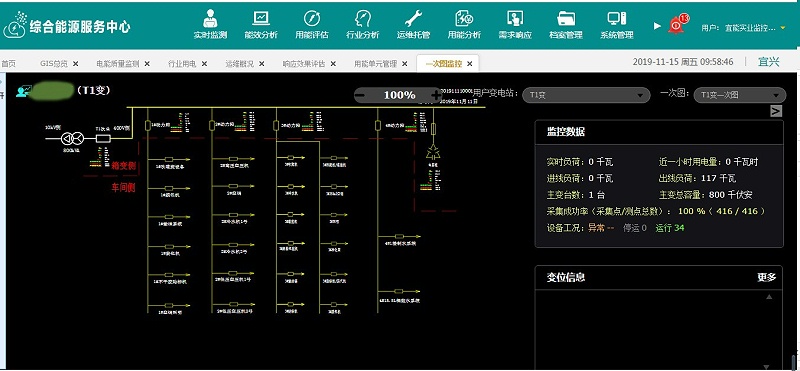
Demonstration of various submenu functions
Share to:


Electricity Solutions for Agricultural Irrigation
Electricity Management Solution for Smart Factories


