Electrical Safety – Solution for School Electrical Safety Management Systems
Case Details
1. Overview
1.1. Project Overview
The Senwei Electronic "Safe Electricity Use" Management Cloud Platform utilizes IoT technology to conduct continuous data monitoring and statistical analysis on key factors associated with electrical fires—such as cable temperature, current, voltage, residual leakage current, and energy consumption. It detects safety hazards in electrical circuits and equipment in real-time (e.g., abnormal cable temperatures, short circuits, overloads, over-voltage, under-voltage, and leakage), thereby effectively preventing electrical fires.
Adhering to the principles of "market-led, government-guided, entity-driven, and socially participatory" operations, the project accelerates the deployment of "safe electricity use" systems. By leveraging technologies such as IoT, big data, and artificial intelligence alongside expertise in electrical safety, the platform employs data mining and analysis to detect hazards early, classify them, and understand their patterns of occurrence and progression. This enables the prediction of hazard trends and the integration of risk factors with socialized service systems. Ultimately, this establishes a safety prevention framework involving four key parties—predictive warning, hazard remediation, socialized services, and government information gathering. This approach enhances the precision of hazard prediction and safety service delivery, strengthens early warning and prevention capabilities regarding electrical fires, significantly reduces the incidence of electrical fires at the Jiangqiao Wholesale Market, and ensures the safety of people's lives and property.
The online service for electrical fire hazard management utilizes big data analytics, IoT technology, and cloud computing to identify, warn against, and manage electrical fire hazards. Through internet technology, it integrates offline service providers to offer comprehensive on-site hazard remediation services to relevant entities, ultimately achieving a significant reduction in the probability of electrical fires in the target area.
2.1. System Structure
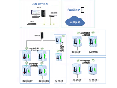
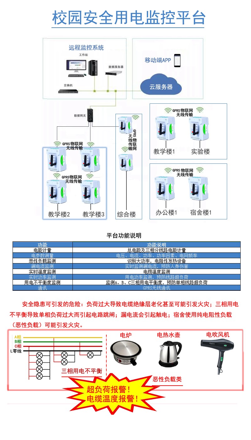
The cloud platform for safe electricity management is designed with a layered, distributed architecture comprising the field device layer, the network communication layer, and the station control management layer. The detailed topology is as follows:
2.2. Electrical Fire Hazard Remediation Model
Leveraging an online "Hazard Early Warning Platform" to collect operational data from electrical circuits, the system uses big data analytics to identify types of electrical hazards. An offline service team provides comprehensive remediation services to ultimately eliminate these hazards. The "Hazard Management Platform" provides regulatory bodies with tools for hazard monitoring, remediation management, and information analysis reports, enabling risk assessment of electrical fire hazards within the region.
System applications include an electrical fire monitoring and early warning system based on real-time monitoring, a hazard analysis and regulatory system based on monitoring data, and the establishment of an offline service framework driven by monitoring data.
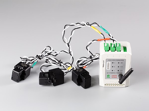
Through stages such as project design, installation, management, commissioning, and operation, the system achieves real-time monitoring of electrical circuits in buildings, enabling functions like data collection, transmission, monitoring, and alarming. Real-time monitoring devices—including smart electrical safety sensor terminals, residual current transformers, current transformers, and temperature sensors—are installed in target power distribution cabinets. Multiple parameters (such as residual current, load current, and cable temperature) are collected and transmitted wirelessly to the platform server.
The system features remote real-time monitoring, alarms for abnormal data, historical data query and statistics, real-time display of dynamic data changes, and analysis of electrical circuit safety hazards and their remediation. Additionally, it supports mobile app access, third-party remote service hosting, remote firmware upgrades, and remote equipment maintenance.
3. Equipment Selection and Introduction
3.1. On-Site Equipment Selection
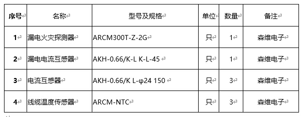
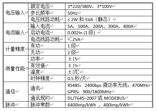
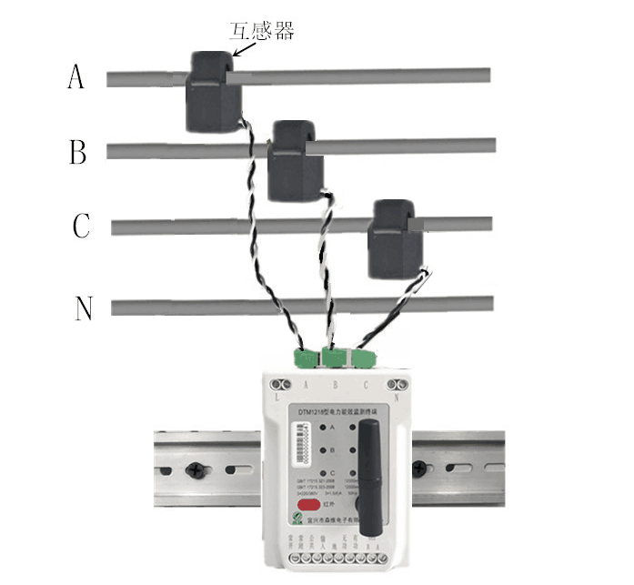
Based on on-site monitoring requirements, the following equipment is mandatory for each circuit.
Option 1: For circuits rated below 100A – Split-core current transformer.
4. Platform Configuration
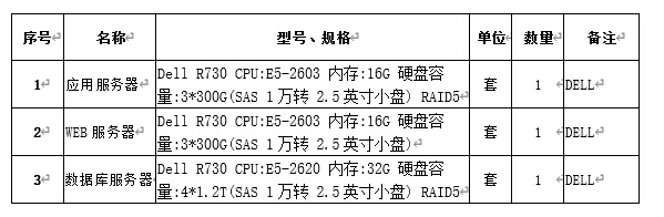
The electrical safety service platform requires three servers for daily operation and maintenance:
A database server to collect and store real-time signals—such as leakage current, cable temperature, current, and power—from the on-site leakage detectors, supporting the generation of trend curves and bar charts;
An application server to handle data visualization and analysis, process various alarm signals, and issue alarm notifications;
A web server to facilitate web-based data access and data encryption.
The server configuration is as follows:
1) The electrical safety monitoring and service system comprises a cloud management platform, PC display terminals, a mobile app, residual current detectors, residual current transformers, current transformers, and other components.
2) The platform displays real-time monitoring data and trend curves for electrical safety parameters (such as residual current, temperature, and current), historical data and trends, and real-time alarm data. It also displays operational metrics such as the number of on-site service visits, hazards resolved, outstanding hazards, unresolved alarms, routine inspections, and product maintenance; monitoring data is archived for over ten years.
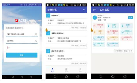
3) The mobile app is available for both iOS and Android; it supports direct calling based on alarm records, facilitating rapid notification of the power-using entity during emergencies.
4) The system automatically compiles statistics and performs analytical assessments of the electrical safety status of various entities and equipment, providing on-demand electrical safety analysis reports.
5) Monitoring and detection terminal products comply with national laws, regulations, and relevant technical standards (GB14287.2 "Residual Current-Operated Electrical Fire Monitoring Detectors" and GB14287.3 "Temperature-Sensing Electrical Fire Monitoring Detectors") and hold "3C" fire safety certification issued by the National Fire Equipment Quality Supervision and Inspection Center.
6) The residual current detector simultaneously monitors parameters such as residual current, four-channel temperature, and three-phase current, and connects to the monitoring platform via wireless mobile networks.
7) The ARCM residual current detector and the Acrel-6000Cloud monitoring platform are covered by insurance provided by the People's Insurance Company of China (PICC), offering a cumulative indemnity limit of 10 million RMB and a per-incident limit of 5 million RMB (covering product liability, electrical fire liability, third-party liability, etc.).
8) The Senwei Electronics electrical safety monitoring platform holds a national computer software copyright.
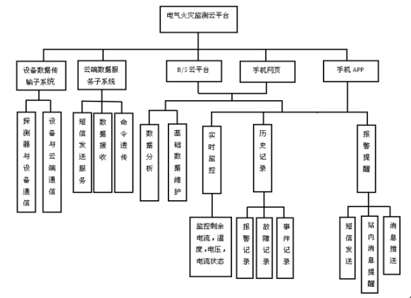
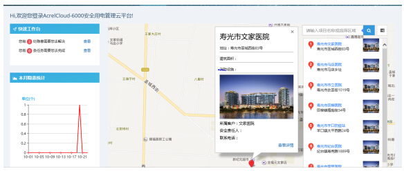
The electrical safety management platform provides an integrated monitoring interface that displays data regarding issues such as leakage, overheating, broken circuits, short circuits, overvoltage, and undervoltage. By centrally analyzing this information, the system enables maintenance personnel to intuitively grasp the current safety status. The system supports login based on different user roles and accounts.
5.2. B/S Architecture and Mobile Client Support
The system is designed and built using a web-based (B/S) architecture and includes a mobile client for ease of use. Users and authorized personnel from management departments can access the system via the Internet from any location to view information and perform operations within their permission levels; additionally, users can access the system by installing a mobile app (available for both iOS and Android) on their smartphones.
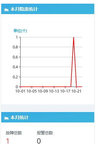
Hazard: Refers to a detected hazard for which a work order has not yet been issued, requiring the assignment of personnel for remediation;
Task: Refers to a work order issued to the currently logged-in user that must be completed to close the loop on hazard remediation.
5.3. Hazard Analysis and Supervision System Based on Monitoring Data
By analyzing multi-dimensional data on key electrical characteristics of power circuits—such as cable temperature, current, and residual current—the system provides a precise reflection of circuit status. It not only detects hazards but also identifies their types, uncovers patterns of occurrence, and predicts trends in their development. The system provides distinct software platforms tailored to different user roles: platforms for responsible parties focus on real-time hazard alerts and proactive control, while platforms for supervisory bodies focus on regional safety assessments and tracking hazard remediation progress. Online services are thus provided to regulatory agencies, local sub-districts, communities, business owners, and tenants.
5.4. Data Presentation
The system classifies, stores, and manages both raw and application data; verifies and analyzes data integrity and accuracy; provides logging and alerting for data anomalies; ensures the uniqueness and authenticity of raw data; and offers comprehensive data backup and recovery mechanisms.


